Gateway
This document contains the hardware technical characteristics, as well as its components. Additionally, there is a complete description of the programming methods and the configuration commands of the meteorological data concentrator device (Iot-LoRa-Gateway). It is worth mentioning that the product is compatible with LoRa communication devices.
Technical Characteristics#
The Lopy4 development board is the central processing unit of the equipment. The main relevant features can be found in Lopy 4 datasheet!.
Electrical#
- Input voltage: 3.5 - 4.2V
- Output voltage: 3.3V, 1.2 A.
- Max Input sink current - GPIO: 12mA
- Input leakage current: 50nA
- Max Output source current: 12mA
CPU#
- Xtensa® dual–core 32–bit LX6 microprocessor(s), up to 600 DMIPS
- Hardware floating point acceleration
- Python multi–threading
- An extra ULP–coprocessor that can monitor GPIOs, the ADC channels and control most of the internal peripherals during deep–sleep mode while only consuming 25uA
Memory#
- RAM: 520KB + 4MB
- External flash: 8MB
LoRa#
- Frequency Range: 137–1020MHz
- Spreading factor: 6 – 12
- Effective Bitrate: 0.018 – 37.5 kpbs
- Sensitivity: –111 to –148 dBm
WiFi#
- 802.11b/g/n 16mbps.
Bluetooth#
- Low energy and classic
- Compliant with Bluetooth v4.2 BR/EDR and BLE
- +12 dBm transmitting power
- Standard HCI based on SDIO/SPI/UART specification
GPRS#
- supports command including 3GPP TS 27.007, 27.005 and SIMCOM enhanced AT Commands.
- Working Voltage: 3.5 4.2V
- Quad-band 850/900/1800/1900MHz
- Send and receive GPRS data (TCP/IP, HTTP, etc.)
- low current consumption - 1mA in sleep mode.
Power Supply#
- Lithium battery 3.7V 6000mAh.
- MPPT charge controller for 3.7V lithium batteries.
- Solar Panel 6V.
Hardware component description#
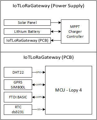
The hardware is integrated into a Printed Circuit Board (PCB), with the Lopy4 development module as its main component. The PCB is responsible for carrying out control, storage, and transmission tasks. The other device peripherals (RTC ds3231, FTDI Basic, DHT22, and GPRS SIM800L) are connected to the aforementioned Central Processing Unit (Lopy4).
In addition to the PCB, the device has a Lithium battery, an MPPT charge controller, and a 6V solar panel.
 |
|---|
| IoT LoRa Gateway Architecture |
Lopy4 connections#
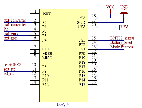
The Lopy4 board has 28 pins, including the power pins and a 3.3V output. The arrangement and connections with other peripherals are detailed below:
- P0: Rx P1: Tx. UART communication with the FTDI Basic.
- P2: Boot pin to update the firmware.
- P3: Tx P4: Rx. UART coomunication with the SIM 800L.
- P8: Boot pin for SIM 800L.
- P9: SDA P10: SDL. I2C communication with the RTC ds3231.
- P21: Operating mode control pin.
- P22: Battery voltage level reading pin.
- P23: DHT22 sensor signal reading pin.
 |
|---|
| Lopy4 pin connections |
Peripheral Connections#
DHT22#
The internal temperature and humidity sensor are connected to an MCU digital pin, configured as an input. A pull up resistor is also connected to the signal output, as shown in the following figure:
 |
|---|
| DHT22 pin connections |
GPRS SIM800L#
This peripheral uses the UART protocol to connect to the MCU; further, it uses a digital pin to control the start, shown in the figure below. It is powered by a lithium battery (3.7V - 4.2V).
 |
|---|
| GPRS Sim800L pin connections |
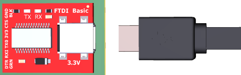
FTDI Basic#
The module connects to the MCU through the UART protocol and shares the reference to GND.
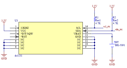
RTC DS3231#
This peripheral is connected to the MCU through the I2C protocol; two pull-up resistors are used in the communication pins (see figure below). It also has a small battery to power it in case of power failure.
 |
|---|
| RTC DS3231 pin connections |
Installation and Start-up#
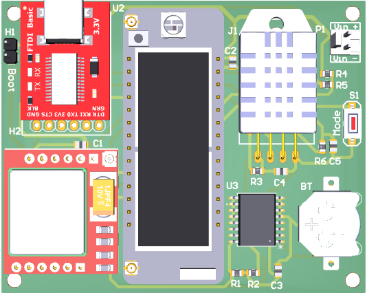
This section introduces the device start-up; it also gives a brief description of the software to be used and describes the commands required for the configuration. Below is a 3D view of the LoRa Gateway IoT device and details of each component:
- U1: GPRS module SIM 800L
- U2: Lopy 4
- U3: RTC DS3231
- J1: Temperature and humidity sensor DHT22
- P1: Power In connector
- H1: Jumper conector - boot mode selector.
- H2: usb to serial converter.
- S1: Operating mode selector button
 |
|---|
| IoT LoRa Gateway Device |
Start-up#
It is necessary to download the software for management and programming to start configuring the Gateway as indicated on the webpage Documentos de Pycom Lopy4. We can work with both "ATOM" and/or "Visual Studio Code" software.
In the case of using Windows, it is necessary to download the Usb-serial converter drivers from the website FTDI Chip -VCP. In this way, we will have the corresponding COM port.
Once the software components have been installed, we have to connect the board to the power supply through P1 and a PC with a micro USB cable for data use through P2.
The board has a LED that indicates the normal mode startup of the board and the mode in which it is running. The sequence starts with the RED LED on for 1 second, which means that the board enters standby mode (Configuration mode).
 |
|---|
| USB connection |
Note that it is necessary to open the programming environment to add the COM device and configure the gateway device. The steps to follow are detailed below:
- Open Pymakr.
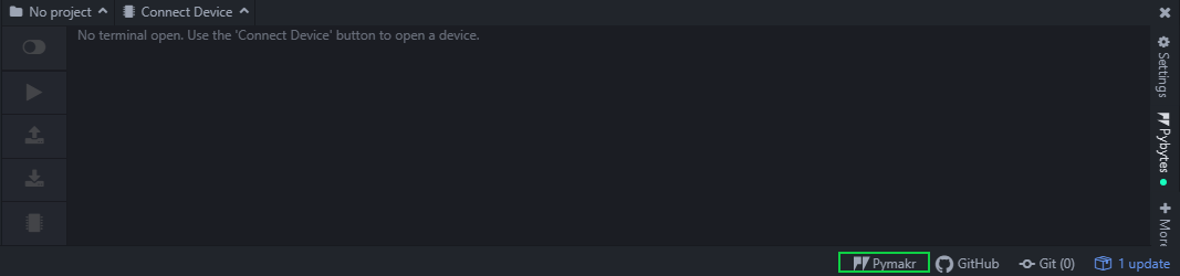 |
|---|
| Pymakr package opened |
- Open Global Settings.
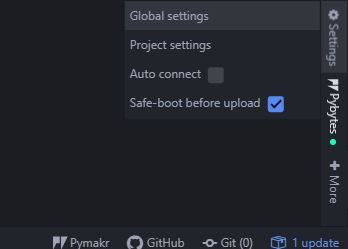 |
|---|
| Open Global Settings |
- Set the corresponding COM port to verify from the device manager.
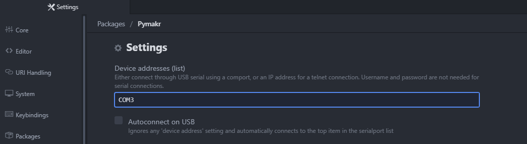 |
|---|
| Set COM port |
- Open COM port from Connected Devices.
 |
|---|
| Open COM port |
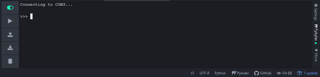 |
|---|
| Console ready for configuration |
System Operation#
The system can operate in 3 modes, which are described below:
Configuration mode#
In configuration mode, the system is waiting to execute some commands. When the software is loaded for the first time, the system will enter this mode, and a RED LED will light up as an indicator.
The system automatically performs the following process:
- Synchronizes time and date from the RTC DS3231.
- Activates LoRaRaw mode.
- Waits for command execution.
First, we must execute the following command to configure the NTP server's time synchronization and upload it to the RTC DS3231.
The device must remain in this operating mode to synchronize the time and date of the nodes. Once the nodes are synchronized we can switch to LoraWan mode to send packets to the server for which we use the following command.
To enter the run mode, execute the following command.
Run mode - Active console.#
This is the mode in which the device will remain constantly running. The device will perform the following steps:
- Time and date synchronization.
- Alarm initiation for packet transmission.
- Connection to the LoRaWan server.
- Wait for node transmission for 2 minutes.
- Go into deep sleep mode.
Run mode - Inactive console,#
This is the mode in which the device will remain constantly running. The device will perform the following steps:
- Time and date synchronization.
- Disable console.
- Alarm initiation for packet transmission.
- Connection to the LoRaWan server.
- Wait for node transmission for 2 minutes.
- Go into deep sleep mode.
Configuration Methods#
GPRS SIM800L mobile connection#
The time synchronization should be considered first to configure the device. The synchronization is done through the Network time protocol (NTP) and the GPRS SIM 800L.
The following are the synchronization methods with the GPRS SIM 800L module.
- Response: +CSQ: rssi, ber
- rssi
- 0: -115 dBm or less
- 1: -111 dBm
- 2...30: -110... -54 dBm
- 31: -52 dBm or greater
- 99: not known or not detectable
- ber (in percent):
- 0...7 As RXQUAL values in the table in GSM 05.08
- 99 Not known or not detectable
- rssi
- Response: +SAPBR: cid, Status, IP_Addr
- cid : Bearer profile identifier
- Status
- 0 Bearer is connecting
- 1 Bearer is connected
- 2 Bearer is closing
- 3 Bearer is closed
- IP_Addr: IP address
- Response: +SAPBR: cid, Status, IP_Addr
- cid : Bearer profile identifier
- Status
- 0 Bearer is connecting
- 1 Bearer is connected
- 2 Bearer is closing
- 3 Bearer is closed
- IP_Addr: IP address
- Response: (year, day, month, hour, minute, second, millisecond, None)
Real time clock (RTC) ds3231#
The external real-time clock (RTC) ds3231 is the one that will keep the system synchronized in time and date due to an independent battery. The methods for synchronization are presented below.
- Synchronizes the external real-time clock (ds3231) with the internal time (lopy 4).
- Response: (year, day, month, hour, minute, second, millisecond, None)
- Obtains the date and time from the external real-time clock (ds3231).
- Response: (year, day, month, hour, minute, second, millisecond, None)
- Synchronizes the internal clock (lopy 4) with the time of the external real-time clock (ds3231).
- Response: (year, day, month, hour, minute, second, millisecond, None)
Temperature and humidity sensor DHT11#
The sensor reading is carried out by the following method:
- Response: result.temperature
- Response: result.humidity
Scripts#
The system scripts are divided into .py files. These files contain the classes and methods for the correct operation of the system. These files are:
Boot.py#
The first file is called boot.py, which starts the system. This file defines the serial communication to display the console and upload the programs. Additionally, it sets up the program that will start after these configurations. Furthermore, the WiFi module is disabled to reduce energy consumption.
Code: Boot.py
sim800L.py#
ds3231.py#
dht.py#
This file contains the class and methods for the configuration and sampling of the temperature and humidity sensor dht22; it was taken from JurassicPork/DHT_PyCom
main.py#
It is possible to edit versioned docs in their respective folder:
versioned_docs/version-1.0/hello.mdupdateshttp://localhost:3000/docs/hellodocs/hello.mdupdateshttp://localhost:3000/docs/next/hello